Ordinary fuses and photovoltaic fuses are both important components for circuit protection, but they have several differences in terms of application scenarios, tech...
More >>Model:ATPVSO-40
Pole:4P
Rated voltage: 1000VDC to 1200VDC
Rated current: 32A
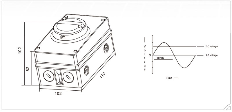
Diemsions: 111x104x161mm
Waterproof degree: IP66
Breaking capacity: 1000/1700
Certificate: CE/IEC/ROHS
Standards:IEC60947-3
Ambient temperature: -40
Insulated voltage: DC1500V
Operating environment
● Altitude of 2000 meters and below, above 2000 meters need to derate for use, other special requirements, please contact the manufacturer;
● Ambient air temperature -25 ℃ to +40 ℃, 24-hour average temperature does not exceed +35 ℃;
● When the ambient air temperature is higher than +40°C or hell -25°C, please contact the manufacturer;
● The inner core of the product is installed in the distribution box, where there should be waterproof measures.
scope of application
ATPVSO series rotary isolating switches are mainly used for line isolation between photovoltaic modules and inverters in photovoltaic power generation systems. The waterproof performance of this product reaches IP66, and the inner core of the DC isolating switch can be installed inside the inverter for inverter incoming line control.
use environment
● Altitude of 2000 meters and below, higher than 2000 meters need to derate for use, other special requirements, please contact the manufacturer:
● The ambient air temperature is -25°C to +40°C, and the 24-hour average temperature does not exceed +35°C;
● When the ambient air temperature is higher than +40 degrees or hell -25 degrees, please contact the manufacturer;
● The inner core of the product is installed in the distribution box, where there should be waterproof measures.


A1l photovoltaic installations must have a DC Switch to disconnect the DC/AC inverter from the photovolaic panels in accordance with IEC 60947-3.
The switch has 4 separate poles.
Links can be used to change the way that the poles are connected. Links can be used to change the way that the poles are connected.
Interconnection of the poles dominates the load that the switch can connect and break.
As the number of poles increases, the total load switching capacity of the device increases.
| name | unit | ISO SWITCH | |||||
| Current Rating | A | 16 | 25 | 32 | 63 | 100 | |
| Isolation Voltage | VDC | 1500 | |||||
| Rated operating current DC21 B | |||||||
| 2 Pofes connected in secies | 500VDC | A | 16 | 25 | 32 | 63 | 100 |
| 2 Poles in paraliel connected in series with 2 Poles in araliel | 500VDC | A | 29 | 45 | 50 | 80 | 160 |
| 750VDC | A | 13 | 16 | 20 | 38 | 80 | |
| 1000VDC | A | 9 | 11 | 13 | 26 | 50 | |
| 3 Poles connected in series | 500VDC | A | 16 | 25 | 32 | 63 | 100 |
| 750VDC | A | 16 | 25 | 32 | 63 | 100 | |
| 4 Poles connected in series | 500VDC | A | 16 | 25 | 32 | 63 | 100 |
| 750VDC | A | 16 | 25 | 32 | 63 | 100 | |
| 1000VDC | A | 16 | 25 | 32 | 63 | 100 | |
| Protection ciass | IP66 | ||||||
| Mechanical life | Million times | 32 | |||||
| Rated short-circuit current (Is) 2}4/2+2 H | A | 800/1300 | 900/1500 | 1000/1700 | 1100/2000 | 1200/2500 | |
| Breaking capacity | Icm | 800/1300 | 900/1500 | 1000/1700 | 1100/2000 | 1200/2500 | |
It is important to ensure that allelectrical connections (including factory connections) are tight enough that all terminal screws are tightened firmly.
It is recommended that for DC, multi-stranded cable, crimp ferules are used to ensure that the wires do not become loose. Loose cables can cause excessive watt loss and generate excessive heat causing serious damage to the switch.
After instaling and wiring the switch, the testing switches, on and off several times, are necessary for users and user must feel and hear the positive snap actions.
If the switch cannot be felt and heard to operate correctly then it is important that the switch i-s cannot be instaled.
If you have any questions or comments, we are ready to help. Please allow 24 hours of response time in working days
GET A QUOTE